


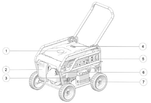
Item | Component | Description |
| 1 | Fuel Tank Cap | Provides access to the fuel tank. |
| 2 | Air Filter | Filters impurities from the air to reduce wear of the engine. |
| 3 | Engine Oil Indicator Dipstick | Provides access to the oil tank and measures the oil level. |
| 4 | Fuel Gauge | Provides indication of the fuel level. |
| 5 | Control Panel | Contains the switches, buttons, indicator panel and receptacles for proper operation of the generator. View table below for additional information. |
| 6 | Recoil Starter | Causes the recoil starter to crank the engine when pulled. Used as a secondary engine starter if the battery does not contain adequate charge to operate the electric starter. |
| 7 | Battery | Operates the electric components of the generator, including electric start and indicator panel. |
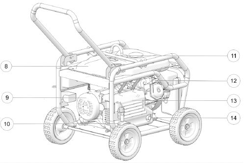
| 8 | Gas Tank | Contains the fuel supply to operate the engine. |
| 9 | Air Intake | Provides air to cool the engine. |
| 10 | Wheel Locks | Locks rear wheels to inhibit motion of the generator. |
| 11 | Lift Mount | Allows for vertical suspension of the generator. |
| 12 | Spark Plug | Ignites fuel and air mixture to start the engine. |
| 13 | Air Exhaust | Dispels exhaust air from cooling the engine. |
| 14 | Muffler | Reduces noise and emissions from engine combustion. The spark arrestor is located on the end of the muffler. |
The choke lever is located above the air filter. The initial position is OFF/OPEN. Turn to the left to the ON/CLOSED position to start a cold engine. Return the choke lever to the initial OFF/OPEN position once the engine has warmed.
Control Panel
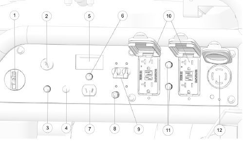
| Item | Component | Description |
| 1 | Fuel Valve Switch | Controls the ignition system and fuel valve. ON opens the fuel valve and allows the engine to be started. It must be ON to allow the engine to operate. OFF closes the fuel valve and shuts off the engine. It must be OFF when the engine is well-cooled and not in use to reduce the possibility of fuel leakage. |
| 2 | Ignition Key Switch | Must be in the ON/RUN position for the generator to operate. |
| 3 | Electric Start Circuit Breaker | |
| 4 | Indicator Light | Will illuminate GREEN when the engine is running. |
| 5 | Hour Meter | |
| 6 | DC Circuit Breaker | |
| 7 | DC Receptacle | Charges 12V DC automotive-type batteries. The DC charging output is not regulated. This receptacle is protected from an overload with a circuit protector. If the DC circuit is overloaded, the protector will open and power to the DC receptacle will cease. |
| 8 | Ground Terminal | Connects to the frame of the generator, metal parts that do not conduct current and ground terminals of each receptacle. Notice: Consult a qualified electrician, electrical inspector or local agency having jurisdiction for local codes or ordinances for the intended use of the generator before using the ground terminal. |
| 9 | 240V Circuit Breaker | Will automatically switch off if a short circuit or significant overload of the generator occurs to the 240V receptacle. If the circuit breaker switches OFF (down) automatically, check that all connected appliances are working properly and do not exceed the generator's maximum output before switching the breaker back to the ON (up) position. |
| 10 | AC Receptacles | Provide four connections for properly rated AC appliances. |
| 11 | AC Circuit Breakers | |
| 12 | 120V / 240V AC Twist- Lock Receptacle | Provides connection for properly rated 120V and 240V AC appliances. |
For more information, see your authorized Polaris Dealer. Find a dealer near you with the Dealer Locator.
More operation and maintenance procedures can be found in your Owner's Manual.
For replacement part numbers, use the online parts catalog.
YouTube® is a registered trademark of Google LLC
Unless noted, trademarks are the property of Polaris Industries Inc.
© 2022 Polaris Industries Inc.


